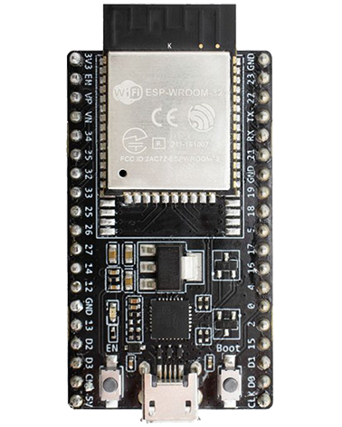
On many development boards with built-in USB/Serial the programming hardware is provided for you and software such as esptool.py can automatically reset the board into bootloader mode using it. However for production boards you may well not want to add components only required at programming time on the board itself.
Off the shelf programming adapters
ESP-Prog
Espressifs own off the shelf programme. Nice simple option – see here.
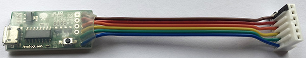
AnalogLamb ESP32 Programmer with CH340 USB to Serial Chip
AnalogLamb ESP32 Programmer with CH340 USB to Serial Chip
Provides 6 pin header including connections for EN and GPIO0 pins meaning you don’t need to provide any programming hardware on your target board.
The TXD and RXD pins cross over (programmer TXD connects with ESP32 RX).
Parts required:
AnalogLamb ESP32 Programmer – analoglamb.com
MTA6 – RS Components 543-7750
7/0.2mm² cable – RS Components 214-0677
15.9mm Clear heatshrink – RS Components 873-9191
Assembled programming adapter:
Ensure you cut away the heatshrink over the “EN” button so it isn’t permanently pressed down.
Use a permanent black marker to mark pin 1 on the connector so its obvious when plugging onto the PCB header.
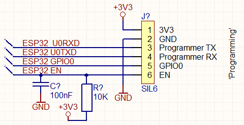
Your PCB’s schematic:
Resources
https://github.com/espressif/esptool/wiki/ESP32-Boot-Mode-Selection
Pins used for programming
GPIO0 (internal pull up resistor)
H / floating = Normal execution mode – “SPI Boot”
L = On powerup will select ROM serial bootloader mode for programming – “Download Boot”
GPIO2 (internal pull down resistor)
If GPIO0 = L (bootloader mode) then GPIO2 must be L / floating in order to enter the serial bootloader
If GPIO0 = H (normal execution mode) then GPIO2 is don’t care.
GPIO12 (internal pull down resistor)
If GPIO0 = L (bootloader mode) then GPIO12 must be L / floating to select flash voltage (VDD_SDIO) 3V3.
If GPIO0 = H (normal execution mode) then GPIO12 can either state
GPIO15 (internal pull up resistor)
H / floating = Normal boot messages output
L = silences boot messages printed by the ROM bootloader
Programming Adapters
In order to achieve programming without having to press hardware buttons you need a USB to serial adapter which brings out the serial RTS and DTR pins using a supported USB to serial IC. DTR is often not brought out by many adapters but the CH340 is one such IC which does and is often used. The reason they are both needed is that tools such esptool.py will manipulate these pins to control the EN and GPIO0 pins directly.
ESP32 Pin    Serial Pin
EN           RTS
GPIO0        DTR
Notes about these pins from our testing:
When resetting (CTRL+T CTRL+R) or when using “make monitor” to start monitoring and resetting the applicaiton:
EN does get pulled low (for about 7mS)
GPIO0 does not get pulled low
5 years ago
I have one question in my custom PCB on the GPIO0 line, I have an I2C_SDA signal with an external 4k7 pull-up resistor. Does the pull-up resistor prevent the programming ?
3 years ago
No since the GPIO0 is meant to be pulled up internally, an external pullup should not interfere.